Resistor Transistor Logic Not Gate . High input results in low output and vice versa. — circuit diagram: The resistors (r1 and r2) in the circuit are. The circuit was designed and simulated using the proteus software. — in this video, i have explained resistor transistor logic rtl with. the basic logic circuit used most frequently in digital logic families is the resistor transistor logic circuit which is a bipolar saturated device. I took supply voltage as. a bipolar transistor switch is the simplest rtl gate (inverter or not gate) implementing logical negation. — the circuit for not gate using a transistor is given below. You can build an inverter/not gate from transistors and resistors. The not gate operates by using a transistor to switch the electrical path based on the input; The resistor transistor logic circuit is shown below. A simple bipolar transistor setup demonstrates the not gate’s working principle, where it inverts the input signal.
from www.numerade.com
a bipolar transistor switch is the simplest rtl gate (inverter or not gate) implementing logical negation. The resistors (r1 and r2) in the circuit are. I took supply voltage as. — circuit diagram: A simple bipolar transistor setup demonstrates the not gate’s working principle, where it inverts the input signal. — the circuit for not gate using a transistor is given below. The resistor transistor logic circuit is shown below. the basic logic circuit used most frequently in digital logic families is the resistor transistor logic circuit which is a bipolar saturated device. High input results in low output and vice versa. The circuit was designed and simulated using the proteus software.
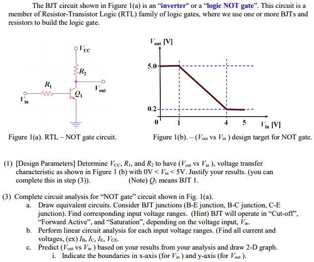
SOLVED The BJT circuit shown in Figure 1(a) is an inverter or a logic
Resistor Transistor Logic Not Gate The circuit was designed and simulated using the proteus software. High input results in low output and vice versa. The resistors (r1 and r2) in the circuit are. A simple bipolar transistor setup demonstrates the not gate’s working principle, where it inverts the input signal. — in this video, i have explained resistor transistor logic rtl with. The resistor transistor logic circuit is shown below. You can build an inverter/not gate from transistors and resistors. I took supply voltage as. the basic logic circuit used most frequently in digital logic families is the resistor transistor logic circuit which is a bipolar saturated device. The not gate operates by using a transistor to switch the electrical path based on the input; — the circuit for not gate using a transistor is given below. — circuit diagram: The circuit was designed and simulated using the proteus software. a bipolar transistor switch is the simplest rtl gate (inverter or not gate) implementing logical negation.
From minucias-angie.blogspot.com
Resistor Transistor Logic Nor Gate Resistor Transistor Logic Not Gate — the circuit for not gate using a transistor is given below. a bipolar transistor switch is the simplest rtl gate (inverter or not gate) implementing logical negation. You can build an inverter/not gate from transistors and resistors. The circuit was designed and simulated using the proteus software. — in this video, i have explained resistor transistor. Resistor Transistor Logic Not Gate.
From partdiagramshamanismif.z21.web.core.windows.net
Logic Gate Circuit Diagram Using Transistor Resistor Transistor Logic Not Gate The resistors (r1 and r2) in the circuit are. — the circuit for not gate using a transistor is given below. The circuit was designed and simulated using the proteus software. You can build an inverter/not gate from transistors and resistors. — circuit diagram: — in this video, i have explained resistor transistor logic rtl with. High. Resistor Transistor Logic Not Gate.
From www.chegg.com
(Part 1) ResistorTransistor Logic (RTL) "NOT” Resistor Transistor Logic Not Gate The resistor transistor logic circuit is shown below. — the circuit for not gate using a transistor is given below. High input results in low output and vice versa. — in this video, i have explained resistor transistor logic rtl with. the basic logic circuit used most frequently in digital logic families is the resistor transistor logic. Resistor Transistor Logic Not Gate.
From circuitspedia.com
What Is NOT Gate Inverter, NOT Logic Gate Inverter Circuit Using Transistor Resistor Transistor Logic Not Gate A simple bipolar transistor setup demonstrates the not gate’s working principle, where it inverts the input signal. The resistors (r1 and r2) in the circuit are. You can build an inverter/not gate from transistors and resistors. High input results in low output and vice versa. — the circuit for not gate using a transistor is given below. The not. Resistor Transistor Logic Not Gate.
From diagrammanualjoanna.z13.web.core.windows.net
Not Gate Circuit Diagram Using Transistor Resistor Transistor Logic Not Gate the basic logic circuit used most frequently in digital logic families is the resistor transistor logic circuit which is a bipolar saturated device. You can build an inverter/not gate from transistors and resistors. — the circuit for not gate using a transistor is given below. — circuit diagram: The resistor transistor logic circuit is shown below. . Resistor Transistor Logic Not Gate.
From partdiagramshamanismif.z21.web.core.windows.net
Nor Gate Using Transistor Resistor Transistor Logic Not Gate High input results in low output and vice versa. The circuit was designed and simulated using the proteus software. The resistors (r1 and r2) in the circuit are. You can build an inverter/not gate from transistors and resistors. The not gate operates by using a transistor to switch the electrical path based on the input; — in this video,. Resistor Transistor Logic Not Gate.
From wiringdbdegualhak9.z14.web.core.windows.net
Logic Gate Circuit Diagram Using Transistor Resistor Transistor Logic Not Gate — circuit diagram: I took supply voltage as. The not gate operates by using a transistor to switch the electrical path based on the input; The resistor transistor logic circuit is shown below. You can build an inverter/not gate from transistors and resistors. — the circuit for not gate using a transistor is given below. the basic. Resistor Transistor Logic Not Gate.
From www.vrogue.co
Transistor Logic And Gate vrogue.co Resistor Transistor Logic Not Gate — the circuit for not gate using a transistor is given below. the basic logic circuit used most frequently in digital logic families is the resistor transistor logic circuit which is a bipolar saturated device. The resistor transistor logic circuit is shown below. High input results in low output and vice versa. a bipolar transistor switch is. Resistor Transistor Logic Not Gate.
From adbu-eee-worldnews.blogspot.com
Department of EEE, ADBU EEE World April 2018 Resistor Transistor Logic Not Gate I took supply voltage as. The resistor transistor logic circuit is shown below. The not gate operates by using a transistor to switch the electrical path based on the input; a bipolar transistor switch is the simplest rtl gate (inverter or not gate) implementing logical negation. — the circuit for not gate using a transistor is given below.. Resistor Transistor Logic Not Gate.
From pijaeducation.com
LOGIC GATES USING TRANSISTOR NOT, AND, OR » PIJA Education Resistor Transistor Logic Not Gate A simple bipolar transistor setup demonstrates the not gate’s working principle, where it inverts the input signal. I took supply voltage as. You can build an inverter/not gate from transistors and resistors. The not gate operates by using a transistor to switch the electrical path based on the input; — in this video, i have explained resistor transistor logic. Resistor Transistor Logic Not Gate.
From www.numerade.com
SOLVED Text (Part 2) ResistorTransistor Logic (RTL) NOR gate Resistor Transistor Logic Not Gate High input results in low output and vice versa. — circuit diagram: I took supply voltage as. You can build an inverter/not gate from transistors and resistors. — the circuit for not gate using a transistor is given below. — in this video, i have explained resistor transistor logic rtl with. The resistor transistor logic circuit is. Resistor Transistor Logic Not Gate.
From www.chegg.com
Solved V cc Figure 2. Resistor Transistor Logic NOT gate. Resistor Transistor Logic Not Gate The circuit was designed and simulated using the proteus software. the basic logic circuit used most frequently in digital logic families is the resistor transistor logic circuit which is a bipolar saturated device. The not gate operates by using a transistor to switch the electrical path based on the input; The resistor transistor logic circuit is shown below. A. Resistor Transistor Logic Not Gate.
From www.youtube.com
Resistortransistor logic YouTube Resistor Transistor Logic Not Gate — circuit diagram: The not gate operates by using a transistor to switch the electrical path based on the input; The circuit was designed and simulated using the proteus software. A simple bipolar transistor setup demonstrates the not gate’s working principle, where it inverts the input signal. You can build an inverter/not gate from transistors and resistors. The resistor. Resistor Transistor Logic Not Gate.
From www.vrogue.co
How To Make Resistor Transistor Logic Gates Custom Ma vrogue.co Resistor Transistor Logic Not Gate The resistors (r1 and r2) in the circuit are. I took supply voltage as. — circuit diagram: the basic logic circuit used most frequently in digital logic families is the resistor transistor logic circuit which is a bipolar saturated device. The resistor transistor logic circuit is shown below. High input results in low output and vice versa. You. Resistor Transistor Logic Not Gate.
From www.electroniclinic.com
Logic Gates in Digital Electronics Complete Guide Electronic Clinic Resistor Transistor Logic Not Gate I took supply voltage as. A simple bipolar transistor setup demonstrates the not gate’s working principle, where it inverts the input signal. The not gate operates by using a transistor to switch the electrical path based on the input; High input results in low output and vice versa. the basic logic circuit used most frequently in digital logic families. Resistor Transistor Logic Not Gate.
From www.youtube.com
Digital Electronics Lab 02 NOT Gate Using Resistor Transistor Logic Resistor Transistor Logic Not Gate You can build an inverter/not gate from transistors and resistors. The resistors (r1 and r2) in the circuit are. The circuit was designed and simulated using the proteus software. The resistor transistor logic circuit is shown below. The not gate operates by using a transistor to switch the electrical path based on the input; High input results in low output. Resistor Transistor Logic Not Gate.
From www.numerade.com
SOLVED The BJT circuit shown in Figure 1(a) is an inverter or a logic Resistor Transistor Logic Not Gate — circuit diagram: The circuit was designed and simulated using the proteus software. a bipolar transistor switch is the simplest rtl gate (inverter or not gate) implementing logical negation. — in this video, i have explained resistor transistor logic rtl with. High input results in low output and vice versa. I took supply voltage as. —. Resistor Transistor Logic Not Gate.
From fixwiringsyntheses.z4.web.core.windows.net
Not Gate Circuit Diagram Using Transistor Resistor Transistor Logic Not Gate High input results in low output and vice versa. the basic logic circuit used most frequently in digital logic families is the resistor transistor logic circuit which is a bipolar saturated device. The not gate operates by using a transistor to switch the electrical path based on the input; a bipolar transistor switch is the simplest rtl gate. Resistor Transistor Logic Not Gate.